40 GHz Multi-Band Lithium Niobate Phase Modulator LNP6118 1310
nm-1550 nm
The LNP6118 is a broadband LiNbO3 z-cut phase modulator designed to
support operation at 1310 nm and 1550 nm. The electro-optic
response (S21) is smooth from DC to 40 GHz. The input fiber is
polarization-maintaining (PM), and the output fiber is standard
single mode fiber; both terminated with FC/PC connectors. The input
FC/PC connector key is aligned to the slow axis of the PM fiber,
which is in turn aligned with the extraordinary mode of the chip.
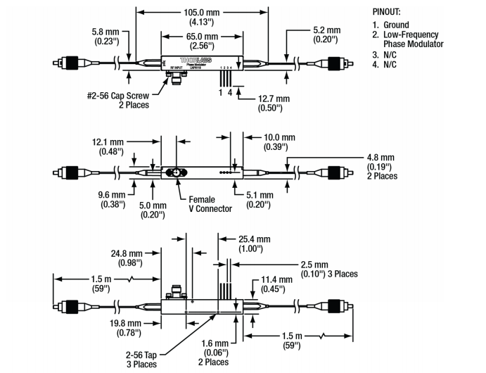
The RF input connector is a field-replaceable 1.85 mm (V)
connector. A separate low-frequency phase modulator, in series with
the RF phase modulator, is available through a separate set of
pins.
The LNP6118 includes an internal polarizer that is aligned with the
extraordinary mode of the chip.
LNP6118 Features:

1. High modulation bandwidth: supports high-frequency signal modulation, suitable for high-speed
optical communication and signal processing.
2. Low insertion loss: Optimized design reduces the energy loss of the optical signal
during modulation.
3. High phase modulation accuracy: provides accurate phase control to ensure the stability and
accuracy of signal modulation.
4. Wide wavelength range: suitable for a variety of wavelengths (such as C-band, L-band),
compatible with a variety of optical systems.
5. Compact design: Compact package for easy integration into complex optical systems.
6. Low drive voltage: Reduces power consumption and is suitable for high energy
efficiency applications.
Technical Parameter:
| Optical Specifications | Min | Typical | Max |
| Operating Wavelengtha | 1260 nm | - | 1625 nm |
| Insertion Loss (1310 nm) | - | 5.0 dB | 5.5 dB |
| Insertion Loss (1550 nm) | - | 4.0 dB | 4.5 dB |
| Optical Return Loss | 40 dB | - | - |
| Optical Input Power (Extraordinary Mode) | - | - | 100 mW |
| Optical Input Power (Ordinary mode) | - | - | 10 mWb |
| RF Electrical Specificationsc | Min | Typical | Max |
| E/O Bandwidth (-3 dB) | - | 35 GHz | - |
| Operating Frequency Range | DC to 40 GHz (Minimum) |
| RF Vπ (@ 10 GHz) | - | 7.0 V | - |
| RF Vπ (@ 30 GHz) | - | 8.5 V | 9.5 V |
| S11 (DC to 25 GHz) | - | -12 dB | -10 dB |
| S11 (25 to 40 GHz) | - | -8 dB | -6 dB |
| RF Port Input Power | - | - | 24 dBm |
| Low-Frequency Modulator Specificationsc | Min | Typical | Max |
| Operating Frequency Range | DC to 1 MHz (Typical) |
| Vπ (@ 1 kHz) | - | 10 V | - |
a. The modulator is designed for use at the specified wavelengths.
Using the modulator at other wavelengths may cause an increase in
the optical loss that is not covered under warranty. In some cases,
this loss can be temporary; for instance, the increase in loss
caused by shorter wavelengths can usually be reversed by heating
the modulator to 80 °C for an hour.
b. Extra care should be taken while aligning the polarization state
of the optical input to avoid excess optical power from being
launched into the ordinary mode, which will be absorbed by the
polarizer and can damage the modulator.
c. At 1550 nm
| Environmental Specifications | Min | Typical | Max |
| Operating Temperature | 0 °C | - | 70 °C |
| Storage Temperature | -40 °C | - | 85 °C |
| Mechanical Specifications |
| Crystal Orientation | Z-Cut |
| RF Connector | Female 1.85 mm (V) |
| Fiber Type | Input: PANDA Polarization Maintaining
Output: SMF-28®† Single Mode |
| Fiber Connectors | 2.0 mm Narrow Key FC/PC |
| Fiber Lead Length | 1.5 m (Typ.) |
| Fiber Jacket | Ø900 µm Loose Tube |
†SMF-28 is a registered trademark of Corning Incorporated.
Mechanical Drawings:
| STANDARD INPUT FIBER |
FIBER TYPE | PM |
| CONN. TYPE | FC/UPC |
| KEY | NARROW |
| KEY ALIGNMENT | SLOW |
| STANDARD OUTPUT FIBER |
| FIBER TYPE | SM |
| CONN. TYPE | FC/UPC |
| KEY | NARROW |
| KEY ALIGNMENT | N/A |
LNP6118 Application:

1. Optical communication system: used for phase modulation in optical fiber communication to
improve the efficiency and quality of signal transmission.
2. Coherent optical communication: Phase modulation and demodulation of optical signals are realized
in a coherent receiver.
3. Optical sensing: For high-precision optical sensors such as interferometers and
distributed fiber optic sensing systems.
4. Quantum communication: Phase encoding of optical signals in quantum key distribution
(QKD) systems.
5. Laser radar (LiDAR) : Used for phase liDAR to improve ranging accuracy and resolution.
6. Research experiments: Used in optical experiments and research for phase modulation and
light field regulation.


